Tim Cann: Astro-imager | SRO Chief Engineer | IT Consultant
The primary telescope at SRO is a fork-mounted, 30-inch (0.76-m) Newtonian-Cassegrain reflector designed for multiple focal ratios of f/6 (Newtonian focus) and f/25 (Cassegrain focus). Upon its completion in 1963, the Stony Ridge's 30-inch telescope was the eighth-largest telescope in California, and some believed to be the largest amateur telescope in the world. As new technologies developed through the years, the members of the Stony Ridge Observatory endeavored to keep pace. Timothy Cann has been a longtime SRO and since 1979 its chief engineer. He has been a member of SRO's board of directors since 1981. Over the years he has continued to keep the parts of the mechanism called Stony Ridge Observatory repaired, maintained and moving forward.
Tim Cann’s first upgrade was to convert the telescope's electrical system, a 28-volt DC system, to a110 -volt AC system. Later the addition of a digital computer interface allowed the off-the-shelf telescope control software to read the telescope's position by adapting the mount's chain drives to work with Software Bisque's TheSKY, writing the windows computer control software and TELEAPI device support in C.
In 2005, Stony Ridge members began to encounter problems involving the tracking operation of the telescope that had operated for over 40 years without any major problems. After spending almost a year of unsuccessfully trying to determine the source of the problem, Timothy Cann recommended it was time for a major drive system upgrade to the telescope.
T. Cann is a professional IT consultant with the passion and skills to produce high-precision machine work. The new harmonic drive system for the SRO telescope was designed and built at Chronosmount, Inc., Tim Cann's machine shop in Temecula, CA. Chronosmount, Inc. is dedicated to developing and manufacturing the Chronos equatorial mount, a new, advanced telescope mount system based upon harmonic drive gearing.
To learn more about Chronosmount, Inc. visit the website at: www.chronosmount.com.
As an experienced astro-imager Tim Cann created this website in 2003 to share his photographic experiments using four different manufacturer's mounts and six different OTA's in addition to his self-built ones as well as blog about what he was doing at SRO. Sometime after 2006 this site’s domain expired. When I discovered the domain was available I decided to purchase it with the goal of recreating at least some of its content from archived pages. Unfortunately none of the images from 2003-2005 pages describing Tim’s experiments with digital development methods for making CCD images look like film images were retrievable. However I have included some of his comments. In addition I have added his informative 2006 comments documenting his efforts to use harmonic drives on an equatorial telescope mount.
While Cann was dealing with the telescope, lenses, and other technical issues at the Stony Ridge Observatory, I was dealing with building a website that offered a different type of lenses, specifically replacement eyeglass lenses. Unlike Tim, the customers to this website could just mail in their glasses and have their lens replaced with high quality lens made from plastic and polycarbonate, to high index, Trivex, and even glass. They could order single vision, progressive, bifocal, and trifocal replacement lenses. All their prescription eyeglass lenses are made in the USA with one of the world’s largest lens makers. If the customer needed their Ray Ban eyewear lenses replaced with a new prescription- no problem. All they needed to do was mail in the frames, the new prescription along with a contact number so an optician could call to discuss the best, high quality lens choices and options for their needs. I love my round Ray Bans and plan to keep them for a while, so I will definitely use this site when my favorite frames need new lenses. I bet there were times when the SRO would have liked to be able to order their specializes equipment in such a quick and simple manner!
I am a fan of SRO and in awe of what Tim Cann has accomplished as the primary mechanical and computer support for SRO and as an astro-imager. Please view this site in its historical context.
++++++
2006 Posts
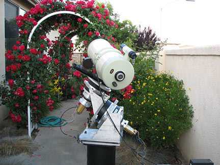
This website documents my efforts to use harmonic drives on an equatorial telescope mount. The ultimate goal is to replace the drives at Stony Ridge Observatory (SRO). But, to keep my sanity, I've decided to build a complete telescope in my back yard, using the same drives that will ultimately be attached to SRO's 30” fork mount (http://www.stony-ridge.org). The testing will occur here.
This is a running log of the project's progress:
May 31, 2006 First Light!
++++++
June 3, 2006 You Don't Know Until You Know!
Since the success of the “First Light” night, it's been a struggle! To say the least. So let me give you the good news before the I tell you of the saga of how we got here. The good news is that last night (June 2) I was able to:
- Use the go-to functions of the Bisque Telescope Control System (BTCS)
- Perform four T-Point models
- Polar align the mount using T-Point
- Complete the hardware installation of the mount
How this all came to be is best summarized by: You don't know what's wrong until you really know what's wrong. Sort of like your feelings when you've misplaced your car keys saying when you finally find them: “Now I know where they were.”
First some background. The harmonic drives are each made up of two drives attached in tandem. The first, on both RA and Dec provide a 50:1 reduction and is the stage that was manufactured to accept the Pittman brush-less servo motors that came with BTCS. The second harmonic drive, the one that will attach directly to SRO, provides another 160:1 reduction. These two drives, or stages, give a total reduction of 8,000:1 and was the design point on which I've based all of my calculations.
(What makes a motor a “servo motor” is the addition of an encoder to the drive shaft. This encoder communicates with BTCS and helps it keep track of where the telescope is pointing.)
The encoder on each drive divides each motor revolution into 2,000 parts which along with the 8,000:1 reduction produces 16,000,000 identifiable parts (BTCS calls them Tics) of a 360 degree circle. That means that BTCS can theoretically position the drives to an accuracy of 0.081 arcseconds. (The encoders currently on SRO divide a circle into 36,000 parts.)
So, given these details which I entered into the BTCS setup screens, the system should have been able to have properly gone from the Moon to Saturn without much difficulty. (They were quite close together on Thursday.) Instead, BTCS moved the telescope (what appeared to be) about double the required distance. Well that did not make any sense to me and it didn't make any sense to Steve Bisque either! We have been debating this for two days and, not any surprise, Steve say's: “BTCS cannot make such an error.”
On top of that, in my early hours of testing, BTCS would shutdown (reboot) almost immediately when executing a high speed slew. Rebooting takes about 10 seconds and my blood pressure was rising each time it did that (beep-beep-beep out of the controller)!
What I discovered about 2:30 am this morning is that the two harmonic drives we have are not the same ratio! Yep, instead of sending me two drives each with 8,000:1 reductions, the RA drive is 5,000:1, which explained why the mount was going too far. (The control system would say, to go to Saturn: move 375,309 tics when it should have been telling it to move 234,568 tics.) Duh! And I was blaming Steve Bisque. Hopefully he'll have a laugh about it when I tell him on Monday.
As for the reboot problem, that one still needs work. I've been able to work around the problem by restricting the maximum slew speed. I believe we'll be able to work that one out.
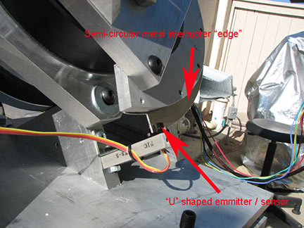
More hardware was added yesterday to complete the installation. Some of you have been asking about my e-mail about pointing accuracy. BTCS finds “home” by using two semi-circular pieces of metal, one mounted on each axis. BTCS seeks out the end of each piece of metal and when it finds it, calls that home. (In much the same way we home SRO by pushing the button on the computer when the scope is anchored down.) This all works because the computer knows the correct time.
++++++
June 5, 2006 CCD Test Images
Last night was a very successful experiment that had a single goal: test the harmonic drives under the most demanding of tasks, CCD imaging. A byproduct of these tests was to verify the drives' ability to be guided, and of course, to be able to find objects, and center and focus them. The results: the drives passed with flying colors, in fact, more successfully than I could ever have hoped. Where can I buy one of these for my backyard?
Not to go over things that are already on this website, but, please allow me to review:
The images were taken at 2600mm focal length, just over ½ of SRO's. Polar alignment was close, but certainly could be made closer with T-Point. Both azimuth and altitude were about 1 arcminute off the pole. And, the German equatorial mount was not balanced, in fact by most measurements it was terribly out of balance; there were no counterbalance weights at all. On my Paramount it takes 40lbs of counterweights to balance the same OTA and cameras, and that does not take into account the fact that the harmonic drive on the Dec axis weighs 37lbs and is on the same side of the RA axis as the telescope. Try that with a worm-and-wheel gear system. Neither RA or Dec were balanced
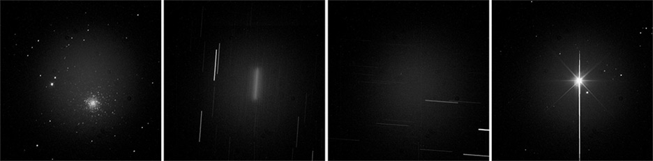
Now, on to the images. Remember, these images were taken to test the harmonic drives, not to create pretty pictures. Note: these images had no dark frames or flat frames applied, no callibration, which is why the center area is not completely black like the edges.
Equipment:
- Takahashi CN-212 Cassegrain, 2600mm focal length prime focus
- SBIG STV autoguider, 100mm focal length f/4 imaging lens
- SBIG ST-1001e CCD camera, 24 micron pixels, 1024x1024 array
- Images were taken at –10 degrees C.
- Harmonic drive German equatorial mount, 5,000:1 RA, 8,000:1 Dec
- Bisque Telescope Control System (BTCS) w/Pittman Series 5433 brush-less servo motors
This is a 60 second exposure of Regulus. Regulus is badly bloomed, as would be expected.
Now, let me spend a few minutes talking about the experience of using the harmonic drives. I've had the pleasure of using a number of very fine telescope mounts: Bisque's Paramount, Takahashi EM-200 and the usual array of Celestron and Meade mounts. At no time did I have to center Regulus or M53. The process went like this:
- Power up the mount
- Tell BTCS to find home
- Use TheSKY to tell the telescope to go to Regulus (it was about 20 degrees west of home)
- Take the image
- Use TheSKY to tell the telescope to go to M53 (it was about 45 degrees east of Regulus
- Take the rest of the images
Both objects were perfectly centered in the field of view of the CCD camera. At no time did I have to “Sync” on a known star. The homing procedure was ample alignment. One more experience that is totally new to me. Before taking these images I used a Canon 20D to take some "preliminary" images. I'd mounted and connected the 20D before homing the telescope. HOWEVER, the change to the SBIG ST-1001e was accomplished with the mount guiding on a star near Regulus! That's right, I made a major camera change including all of the extra hardware (threaded adapters, Optec IFW, SBIG camera and it's cables) all while the STV was doing it's thing. Never once did the STV loose the guide star.
So, what's next? Certainly I'd like to perfect the polar alignment. Also on the agenda is to create a T-Point model to measure pointing accuracy.
In short: I could not be more pleased!!
++++++
June 5, 2006 Down for Repairs
The out-of-spec harmonic drive is on its way back to Hauppauge, NY. The vendor was quite apologetic about their mistake. Their inventory confirmed that they had shipped the wrong ratio.
It is important that both harmonic drives be the same ratio because we want the high-speed-slew to be the same speed for both axes. I decided, and the vendor agreed, that we would make the Dec drive 5,000:1 instead of making the RA drive (the one that was shipped wrong) 8,000:1. Everything that I've written up to this point says that the ratios are 8,000:1, so those of you who are keeping track, and keeping notes, need to change them. When we get done, both axes will be 5,000:1 with a corresponding pointing accuracy of 0.129 arc seconds (instead of 0.081) as reported earlier. Bisque recommends a ratio of between 2,000:1 and 8,000:1, so this change will keep us within their recommendations. By the way, the vendor has committed to having the changed Dec drive back to me before the weekend. So, I'll be unable to do any more testing until it's back.
While dismantling the setup this morning I discovered that the ST-1001e SBIG camera was not anchored well, so it looks like my unguided image was “operator error” rather than a problem with the drives. Charlie was the first to point out my mistake. I'll plan to confirm this when we're back on-line.
The stars are clearly two separate round images, confirming that the camera moved during the exposure. We'll see if a 5 minute unguided image produces nice round stars instead of this mess. It is not unreasonable to expect a properly set up system to be able to produce round stars unguided in an exposure only 5 minutes long. Before I do this test again, I'll plan to work on polar alignment more, and to set the Siderial rate more accurately.
++++++
June 15, 2006 Ugh... Lots of Words
The last week has been very busy! The corrected harmonic drive assembly got here last Friday as promised by the manufacturer. By dark Friday I'd reassembled everything and was ready for bear. Before it was completely dark the night-and-early-morning-low-clouds had rolled in, stopping any activity of importance. Fortunately the remaining nights starting with last Saturday have been increasingly friendly to my testing. Most nights I was out from about an hour before dark till about 10 or 11. Twice I was back up at 3 or 4 to do more. Beth has been understanding, sort of.
I had a number of goals for the week and I believe as much has been accomplished that could have been with me still working during the day. I took several more images, one which I'll share with you is a 30 minute guided and calibrated image of M51.
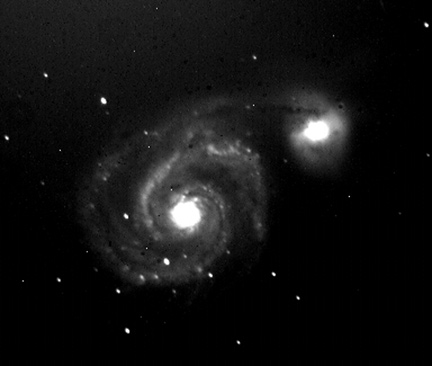
I've done a number of additional T-Point models with great success. Pointing accuracy has been as good as I've ever experienced with a robotic telescope mount. With the camera attached I've been able to slew to any object desired without having to locate and center the object, it was simply there in the camera. This has even been true when the mount must switch sides (a trait of German equatorial mounts but not fork ones). And there has been continued success with guiding using the Santa Barbara Instruments STV auto-guider (which the M51 image attests to). Using the STV as my auto-guider insures that there is always a guide star, which makes photographing a real pleasure. Note: the STV is guiding a 2,600mm telescope using a 100mm lens to image the guide stars. This is probably too short for this long a focal length imaging system and will also be too short for SRO's 4,500mm focal length. I will plan to guide through a longer focal length telescope as my testing continues.
It has turned out that my assumption that the multiple-star-images in the unguided picture (see the June 5, 2006 CCD Test Images page, second picture) was not a loose camera mount, but is in fact uneven tracking. Verification of that was simple: take more images unguided with the camera firmly attached. The real challenge has been dealing with BTCS' insistence on shutting down during high speed slew. This has been an intermittent issue from the beginning and this past week has given me the time and concentration to get my arms around it.
To explain in detail, please let me go over a number of things about our setup. (This was covered on the June 3 posting, I'll repeat it here, before going on, changing the gear ratios to reflect the change made last Friday):
I will be using a number of acronyms, so let me define each of them now for your reference:
BTCS – (Software Bisque's) Bisque Telescope Control System, the electronics and software that will replace the hardware and software that currently controls the chain drives at SRO.
PEC – Periodic Error Correction, a built-in capability of BTCS that enables modeling the periodic error inherent in gear systems that repeat on a very specific cycle. Even the low cost computerized telescopes from Celestron and Meade have PEC.
Tic – Servo motor jargon used to describe the electrical pulses generated by the encoder. Our servo motors generate 2,000 tics per motor revolution. Think of it as a very fast clock tic.
T-Point – Software included with BTCS that allows us to model the polar alignment, harmonic drive gear inaccuracies and telescope mount flexure to give us more accurate pointing.
TheSKY – Software included with BTCS that is an on-computer-screen star chart. TheSKY interacts with BTCS to let us point at an object on the computer screen, click on it, and tell the telescope we want it to slew to that object.
The harmonic drives are each made up of two harmonic drives attached in tandem. The first provides a 50:1 reduction and is the stage that was manufactured to accept the Pittman brush-less servo motors that came with BTCS. The second harmonic drive, the one that will attach directly to SRO' mount, provides another 100:1 reduction. These two drives, or stages, give a total reduction of 5,000:1 (50 x 100).
(What makes a motor a “servo motor” is the addition of an encoder to the drive shaft. This encoder communicates with BTCS and helps it keep track of where the telescope is pointing.)
The encoder on each drive divides each motor revolution into 2,000 parts which along with the 5,000:1 reduction produces 10,000,000 (50 x 100 x 2,000) identifiable parts (BTCS calls them Tics) of a 360 degree circle. That means that BTCS can theoretically position the drives to an accuracy of 0.1296 arcseconds. (The encoders currently on SRO divide a circle into 36,000 parts.)
Now for the new stuff. Imagine what is going on inside BTCS. While it is driving the RA motor to compensate for the Earth's rotation, the encoder is feeding pulses (tics) from the encoder at 2,000 counts per motor revolution. While tracking, the RA motor rotates just over three times a minute. That means that BTCS is receiving over 6,944 encoder tics per minute while tracking. The electronics and software inside BTCS is watching each of those tics and is deciding, real time, exactly what time to tell the motor to move on to the next tic. (It is this design that allows BTCS to correct for pointing errors modeled by T-Point, and for it to correct for PEC. BTCS modifies the “when” to move on to the next tic based on the models.)
Now, this process, real time correction of when to move on to the next encoder tic, is also being performed while the telescope is being slewed. It is this encoder-tic counting that enables BTCS to perform the go-to functions of moving the telescope to a specific object in the sky based on our request for it to go to, for example, M51. BTCS calculates the number of encoder tics from Mars to M51 (for example), turns on the motors (it know which direction), and counts tics until the telescope is pointed at M51. At high speed slew the motors are rotating at up to 4,000 revolutions per minute (RPM). That means that BTCS must watch those encoder tics 8,000,000 times per minute (133,333 times per second). For a computer this is not really all that hard, even though it seems hard to us.
BTCS imposes some safety rules while moving the telescope for us, fast or slow. It knows where the horizon is, for example, and it knows that the telescope tube cannot go so far south that it runs into the fork. We are also able to tell it of arbitrary obstructions that we'd like to avoid. We could, for example, tell it where the trees are so we would be told that a tree is in the way if we ask BTCS to go to an object this is behind one. (I'm not sure how detailed we will ultimately get on this, but we have the flexibility to do whatever we wish.)
As important as all of these BTCS safety rules are, it also looks at a more important one. It watches the amount of power it is supplying the motors and decides, real time, if the power being supplied is “too much.” This means that if the telescope were to run into something that we have not modeled, the amount of power required to move the telescope against that obstruction would be too high and BTCS would shut down before damaging anything. These power limits have been set arbitrarily by BTCS based on the “norms” of the motor and “typical” gearing designs.
And there is the rub. The harmonic drives have a well documented trait called “torque ripple.” I wrote about it in a number of my early project e-mails and studied a number of papers posted on the Internet. It would appear that BTCS is receiving feed back, probably through the motor's electrical feed back mechanisms, or perhaps, through variations in the nature and timing of the encoder tics, that BTCS does not feel is normal, and shuts down.
The shut downs occur at slew speeds only. I've tried to get BTCS to shut down by putting my shoulder under the telescope while it is tracking, the harmonic drives simply ignore my shoulder and drive me into the pavement. So there is something about the nature of the harmonic drives that, at slew speeds, freaks out BTCS and it shuts down with an annoying beep-beep-beep, requiring a re-boot. I've been able to work around this by restricting the maximum slew speed to about 1,000 RPM at the motors. This translates into a horizon-to-horizon slew time of about 3 minutes.
Which in itself is OK, but I'm determined to find a way to fix this. I've been talking extensively with Steve Bisque about finding a way to solve this by modifying the BTCS software to accommodate this nasty trait.
A second item has also surfaced. I'd hoped to model out PEC to improve tracking smoothness. (PEC could correct for the double star images we discussed earlier and I showed images of in the June 5, 2006 CCD Test Images page.) BTCS uses a standard PEC cycle of about 4 minutes. It is supposed to be able to handle a PEC cycle of up to about 10 minutes. Our harmonic drives' PEC cycle is 14 minutes, 24 seconds. Steve Bisque is also looking into modifying BTCS software to allow us to extend the amount of PEC correction. Without PEC, we have no chance of doing unguided exposures longer than about one minute.
Let me be frank. It could be a long road to modifying BTCS to accommodate our use of harmonic drives. Our other choice, use Ed Byers gears, is a choice we should perhaps re-visit. I would like to have an extended discussion about changing direction with Byers gears as the central component of that change. I would like to postpone that discussion to another day. I'd like to give another web page posting that task, perhaps tomorrow.
So what's next? Certainly there needs to be a great deal more discussion with Software Bisque. That might even involve sending them one of our harmonic drives. Last night is used a special utility provided by Steve Bisque that allowed me to graph the motors and encoder tics. I did a number of graphs including normal tracking, slewing at working speeds and slewing leading up to a shutdown. I've sent the results of those tests to Steve for his comments.
We will need to discuss our options which includes Byers gears and perhaps even using BTCS with the chain drives. I will try to put my thoughts together over the weekend and post it in a new wordy web page.
As always, your thoughts, comments and criticisms are welcome!
++++++
June 21, 2006 The Grind
Since my last posting things have been “busy” but not satisfying. For all of you at SRO, allow me to go over some specifics:
The shutdown challenge has not changed. BTCS shuts down at slew speeds above about 30% of maximum. The closer (but less than) the setting is to 30% of maximum, the more often a shutdown occurs.
At 30% the horizon-to-horizon slew time is about 3 minutes.
Even slight temperature changes affect the maximum slew speed that is possible. I don't have much temperature range here, 80F – 90F in the day, 50F during the night. The 30% slew speed maximum works consistently during the heat of the day, while early in the morning when everything has cooled down, 25% or even 20% is necessary to stop the shutdowns. NONE OF THIS MAKES MUCH SENSE TO THE EXPERTS. I've gone over this at nausea with Steve Bisque and with the people at Harmonic Drive LLC (HDSI) and both say this small of a variation in temperature should have no effect.
Steve is away from his office enough that I'm often frustrated by the length of time it takes for a response to a question I've posed, or to his response to information requested by him that I've sent. I've been as quick as possible to answer his questions, or to provide information that he asks for. Steve and I talked last Monday for nearly an hour, but little has come of it.
HDSI on the other hand has been more than helpful. I spent nearly two hours on the phone with them reviewing everything. They even offered to take the drives back to see if reloading a thinner lubricant, or even a different input bearing might help. They offered to swap out the input stage (50:1) from the existing harmonic drive for a planetary drive which would be slightly more efficient. They reviewed all of the technical information about BTCS that is available on Bisque's Web page; they also reviewed the Pittman specification sheets. HDSI concluded that the Pittman motors that Bisque supplied are more than capable of performing up to spec (4,000 RPM) when attached to the systems that they delivered. The bottom line is that they say the possible modifications would have only slight effect on the shutdown sensitivity.
HDSI manufacturers their own servo control electronics and points to their numerous high-precision pointing successes using their harmonic drives. Specifically they point out that their drives operate the antennae on the Mars Rovers and on numerous space satellites. They insist that the “torque ripple” that has been discussed and discussed some more is so small compared to the delivered torque of the Pittman motors, that it cannot be causing the BTCS shutdowns.
I purchased the Molex connectors that BTCS uses to attach the motors and built a break-out harness that allows me to monitor voltage and current levels while the motors are operating (using a storage scope / meter combination). I sent those numbers to Steve as well.
I suggested to Steve that perhaps it would be better if he and HDSI talked directly to take me out of the middle of their respective positions that the other is at fault. I also asked Steve to let me talk to his controller-board engineer to see if he and I might be able to get some things done while Steve is unavailable.
I've spoken to half a dozen manufacturers of servo motor controllers to see if there might be an off-the-shelf piece of hardware that could be mounted between BTCS and the Pittman motors. Some say that what I'm asking can't be done, others say that such an electronic device would have to be designed and built custom. Do any of you know a slick electronics hardware wizard?
I've been passing my time in the evenings doing more photography and T-Point models, but at times I've been asking myself: “What's the point?” until we move beyond the shutdowns.
Let me apologize to all of you because some of my frustration is probably showing here, but I want to keep you all informed about what is going on. This is typical of the process of integrating systems that have never been proven or that have never worked together. It is my opinion that we'll eventually find a solution. I'd be much happier if I had control over everything, but unfortunately we'll need to rely on our vendors to help us get through this.
By the way, and this needs to be said: Steve has offered to refund us our money (less a restocking charge). I still do not feel this is a viable option. BTCS has much superior function to the other electronic control systems I reviewed, and certainly has a larger install base of satisfied customers.
++++++
Posts 2004-2005
Picture Details: No Image Available
Date: 03/17/2004; Seeing: 5; Transparency 5 & hazy; Temperature: 72F
Object: NGC2244 The Rosette Nebula
Telescope: FSQ-106 f/5 w/Orion Deep Sky Filter on EM-200 Temma
Camera: Canon EOS Digital Rebel
Guider: SBIG STV eFINDER
Exposure: 19 - 210 second exposures (summed)
Processing Using ImagesPlus -
>Canon RAW Convert to TIFF(16); Dark Calibrate; Alignment: Transform Only; Adaptive Add;
> Color Digital Development (Breakpoint 1,691, Background Weight 1.06, Background 0);
> Geometric Transforms (Scale) from 3,072 x 2,048 to 768 x 512
++++
Picture Details: No Image Available
Date: 03/29/2004; Seeing: 5; Transparency 5 & partly cloudy; Temperature: 70F
Object: M51 The Whirlpool Galaxy
Telescope: CGE-1100 f/10
Camera: Canon EOS Digital Rebel
Guider: SBIG STV eFINDER
Exposure: 13 - 210 second exposures (summed)
Processing Using ImagesPlus -
> Canon RAW Convert to TIFF(16); Dark Calibrate; Alignment: Transform Only; Adaptive Add;
> Color Digital Development (Breakpoint 14,503, Background Weight 1.00, Background 0);
> Geometric Transforms (Scale) from 3,072 x 2,048 to 768 x 546
++++
NEW DARK FRAME ANALYSIS ADDED AFTER THE SIX IMAGES.
The following six images were taken on three different nights. Here is the information about them that is common to all six:
Date: See each image- No Images Available
Object: M42 The Orion Nebula
- Telescope: FSQ-106 f/5 w/Hutech 2" LPS Filter; EM-200 Temma II
- Camera: See each image
- Guider: SBIG STV through a 105mm f/2.8 lens
- Exposure (each image): 8 - 210 second exposures
Image #2: Nikon D70; IR blocking filter in place; ISO 800
Date: 12/18/2004; Seeing 7; Transparancy 7; Temperature: 60F; Dark Calibrated
Image #3: Canon 20D; IR blocking filter in place; ISO800.
Date: 12/19/2004; Seeing 7; Transparancy 7; Temperature: 60F; Dark Calibrated
Image #4: Canon 20D; IR blocking filter removed; ISO800.
Date: 01/12/2005; Seeing 8; Transparancy 8; Temperature: 49F; NO Dark Calibration
Image #5: Canon 20D; IR blocking filter removed; ISO200.
Date: 01/12/2005; Seeing 8; Transparancy 8; Temperature: 49F; NO Dark Calibration
Image #6: Canon Digital Rebel; IR blocking filter in place; ISO800 :
Date: 12/19/2004; Seeing 7; Transparancy 7; Temperature: 60F; Dark Calibrated
+++++++
Next I'd like to compare the dark frames from each of these three cameras. Please note that dark frames are not effected by the presence or absence of the IR filter.
ImagesPlus' Digital Development function was used to process each of the preceding six images. It was also used to process each of the three dark frames that follow. Specifically, the Auto Button was used to set Digital Development parameters on each of the six images and each of the three dark frames that follow. (This would not be done to dark frames used for calibration.)
Here is a quote from ImagesPlus' help file that describes Digital Development:
Digitial development is a method for making CCD images look like film images. To accomplish this goal three differences between a CCD sensor and film need to be addressed.
1) The gamma curve of a CCD needs to be transformed into the gamma curve of film. The Background and Break-Point controls are used to transform the linear gamma curve of a CCD into the S-shaped gamma curve of film.
2) An edge emphasis effect needs to be introduced into a CCD image. The Edge/Color Emphasis Low Pass Filter controls provide this effect'
3) Color is highly enhanced by modern color film, so a method for emphasizing the color of a CCD image needs to be applied. The Color Emphasis controls provide this effect.
Stretch Parameters:
- Background: The slider sets the low level of the S-shaped gamma curve.
Backgd Wt. This slider is used to adjust the background weight that is applied to the image. A value of 0 means do not apply a background correction. A value between 0 and 2 can darken the background and add contrast to the image.
Break-Point: The slider sets the middle or point of inflection of the S-shaped gamma curve.
The Auto button sets the Background and Break-Point automatically. The resulting image is usually a very good starting point for further refinement. The Auto button is optimized for low contrast underexposed images such as deep sky objects.
++++++
Now, on to the dark frames: For each of the dark frames, pressing the Auto Button on the Digital Development Dialog Box resulted in the following parameters:
- 20D, D70 and Digital Rebel
- Apply to: Red Green Blue
- Operation : Digital Development
- Background : 0
- Background Weight : 1.00
- Sharpening Filter :None
The ONLY parameter that was different between the three cameras was the Break-point parameter. They were:
- 20D: Break-Point = 18D70: Break-Point = 1452
- Digital Rebel: Break-Point = 30
- EOS350D: Break-Point = 300
What I believe this all means is that in the case of the D70 the "...point of inflection of the S-shaped gamma curve..." is higher, nearly a hundred times higher, than either the 20D or the Digital Rebel. Much more noise in the D70. The 350D is ten times that of the old Rebel and over 16 times that of the 20D.
Looking at each of the three dark frames certainly supports the conclusion that the D70 has considerably more noise than the 20D or Digital Rebel. Further, the 20D seems to have a very even distribution of noise across the entire CCD while the Digital Rebel has a decided gradient growing towards the right side and the D70 has a very high level of noies (probably processor heat) to the top left. The 350D has two gradients.
To take this analysis farther, what follows are darks from each of the four cameras. This time the generation of the darks followed this procedure:
1. Take 20-210 second dark frames with the camera's body cover in place and black tape over the vewfinder eyepiece. All 80 dark frames were taken at 71F.
2. Average the last 10 dark frames in each set using the IP operation: Image File Operations | Combine Files | Average
3. The resulting image for each camera was then processed using IP Digital Development, and again as above, using the Auto button to set the parameters. All settings were as above except:
Break Point for
- 20D=250
- 350D=79
- 300D=93
- D70=1689
The purpose of this processing was to make the dark frame's dark-to-light contour visible.
4. Each set of 20 TIFF files were examined using IP Cross Hair Statistics recording the statistics for all 80 images. This data was stored in Excel and then graphed. The graphs follow the dark frames.
5. The same statistics was recorded for the resulting averageddark frames (before the Image Development was applied):
20D
- Min=7
- Max=28059
- Avg=385.402
- Median=137
- Dev=448.252
- Entropy=5.755
- Symmetry=0.319
350D
- Min=7
- Max=50881
- Avg=113.269
- Median=49
- Dev=150.992
- Entropy=5.009
- Symmetry=0.404
300D
- Min=7
- Max=25729
- Avg=146.881
- Median=77
- Dev=166.909
- Entropy=5.114
- Symmetry=0.410
D70
- Min=0
- Max=65535
- Avg=2437.463
- Median=1161
- Dev=2870.238
- Entropy=8.086
- Symmetry=0.432